
Engineering-grade physical fabrication.
We bridge the gap between digital CAD geometry and physical production. Verify our machine tolerances, material standards, and file requirements below.
0.1mm
Laser Kerf Limit
5-Axis
Mill Calibration
1200 dpi
UV Print Resolution
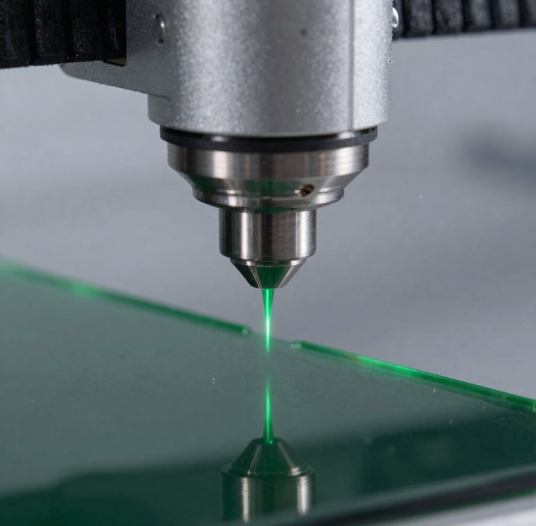
Sub-millimeter repeatability.
Every machine in our facility undergoes daily micrometer calibration. We measure tool wear, laser divergence, and thermal expansion to ensure your physical parts match your CAD files with absolute fidelity.
We work directly with native STEP, IGES, and high-density vector paths, maintaining strict dimensional control across acrylic, metals, engineering polymers, and composite substrates.
File preparation standards.
Submit production-ready files to bypass manual geometry correction, reduce processing overhead, and accelerate your final production run lead times.
3D & CAD Geometry
Vector & Cutting
UV & Engraving
Preferred: STEP, IGES, or solid SLDPRT. Ensure all bodies are manifold, watertight solids with zero open shells. Export at 1:1 scale in millimeters.
Preferred: SVG, DXF, or PDF. Save all cutting paths as hairline vectors. Convert all text to outlines and ensure vector loops are fully closed.
Preferred: High-res TIFF or vector EPS. Minimum resolution of 600 DPI. For multi-layer printing, isolate white ink channels onto a dedicated vector layer.
Ready for physical production?
Submit your finalized CAD files through our secure portal for a comprehensive geometry review and pricing estimate.